On this page I write down some notes about the Intel architecture (x86).
Part of the notes here are for Intel 80186. But some sections are extend with information about modern Intel processors (IA-32, x86-64).
Some information (especially about x86-64) is taken from x86-64 Assembly Language Programming with Ubuntu by Ed Jorgensen.
I’m trying to keep all code examples in NASM (Netwide Assembler) syntax.
There is a good overview of the x86 instructions on Wikipedia.
I keep some examples on GitHub.
General
| CPU Design | CISC |
| Endianness | little |
| Type | Register-memory |
Operation Modes
| Mode | Introduced in |
|---|---|
| Real Mode | 8086 |
| Protected Mode | 80286 |
| Virtual 8086 mode | 80386 |
| Long Mode | x86-64 |
Memory Models
The memory models define how data and code is manged in memory.
Most information in this section is from Calling conventions for different C++ compilers and operating systems.
There is also a good Wikipedia page.
The memory is byte addressable. Data is stored in little endian format. This means that the least significant byte (LSB) is saved on the smallest memory address.
Real Mode Memory Models (16-bit)
This memory models are used in DOS for example.
Tiny
Code and data in the same segment (64 kB). Code starts at
0x100 relative to segment.
Executable has ending .com (instead of .exe).
Small
One segment for code and one segment for data and stack. Both segments have max. size of 64 kB.
Medium
The code can exceed 64 kB (multiple segments). Far function calls are needed.
One segment (of max. 64 kB) for data and stack.
Compact
Code is limited to one segment (64 kB).
Stack is limited to one segment (64 kB).
Data can exceed 64 kB. Far pointers are needed for data.
Large
Code can exceed 64 kB.
Data can exceed 64 kB.
Stack is limited to one segment (64 kB).
Far pointers are needed for code and data.
Huge
Same as large. A data structure can exceed 64 kB by modifying segment and offset when a pointer is incremented.
Protected Mode Memory Models (16-bit)
Win 3.x uses Protected Mode and similar memory models as in Real Mode.
Segment registers contain Segment Selectors instead of physical addresses.
To access data structures bigger than 64 kB the 8 has to be added to the segment descriptor for each 64 kB increment.
On a 32-bit processor a 32-bit offset is used.
32-bit Memory Models
32-bit OS’s (Windows, Linux, BSD, Intel-Mac) use the Flat memory model. Application code uses only one (max. 2 GB) segment.
Pointers are 32-bit signed addresses. Negative addresses are reseved for kernel and drivers.
64-bit Memory Models
Windows
The size of code and static data together is limited to 2 GB. So it’s possible to use RIP-relative addresses. The image base of an executable binary is usually below . Absolute 32-bit addresses are not often used.
Stack and dynamically allocated data (data on heap) can exceed 2 GB.
Pointers are usually 64 bits (sometimes 32 bits).
Negative addresses are reserved for the kernel.
Linux and BSD
Small
Code an static data is limited to 2 GB and stored at addresses below . The compiler can use absolte signed 32-bit addresses.
Stack and dynamically allocated data can exceed 2 GB.
Pointers are 64 bits.
Default memory model in Linux (x64) and BSD.
Medium
Static data bigger than the ‘large-data-threshold’ is stored in a data section that can exceed 2 GB.
Code and smaller static data are limited to addresses below .
Large
Code and data can exceed 2 GB. Addresses are 64 bits.
Kernel
Used to compile the kernel and device drivers.
Addresses must be negative between and .
OS X (Darwin)
The default memory model of the intel-based darwin kernel limits code and static data together to 2 GB. So 32-bit RIP-relative addresses can be used.
Code is loaded to addresses above by default. Addresses below are blocked (pagezero).
Stack and dynamically allocated data can exceed 2 GB.
Pointers are 64 bits. Pointer tables can use 32-bit signed addresses relative to any reference point.
Certain system functions can be accessed in the commpage.
It’s possible to reduce the size of pagezero to place code below so that absolute 32-bit addresses can be used.
Registers
General-Purpose Registers
| 64-bit | 32-bit | 16-bit | 8-bit | Purpose | Notes |
|---|---|---|---|---|---|
| rax | eax | ax | al | General-Purpose Register (GPR) | Accumulator for IN/OUT (AX or AL). Can be used as 8-bit registers (AH/AL). |
| rbx | ebx | bx | bl | General-Purpose Register (GPR) | Base index (array). Can be used as 8-bit registers (BH/BL). |
| rcx | ecx | cx | cl | General-Purpose Register (GPR) | Only register that can be used for LOOP. Can be used as 8-bit registers (CH/CL). |
| rdx | edx | dx | dl | General-Purpose Register (GPR) | Needs to contain port address for IN/OUT. Extend precision of accumulator. Can be used as 8-bit registers (DH/DL). |
| rdi | edi | di | dil | Destination Index | Destination for string operations. |
| rsi | esi | si | sil | Source Index | Source for string operations. |
| rbp | ebp | bp | bpl | Base Pointer | Often used as Frame Pointer (pointing to current stack frame). |
| rsp | esp | sp | spl | Stack Pointer | Points to the top of the stack. |
| r8-r15 | r8d-r15d | r8w-r15w | r8w-r15w | GPRs | x86-64 adds new GPRs. |
The first four GPRs can be accessed as two 8 bit registers. i. e: bx’s high byte can be accessed as bh and low byte as bl.
Segment Registers
These registers are used in real mode and protected mode for memory segmentation.
| Register | Purpose |
|---|---|
| cs | Code Segment |
| ds | Data Segment |
| ss | Stack Segment |
| es | Extra Segment |
Special Registers
| Register | Purpose | Notes |
|---|---|---|
| rFlags | Status Register | Carry Flag, Overflow Flag, Zero flag… |
| rip | Instruction Pointer | Points to the next instruction (cannot be directly accessed) |
Values after Reset
| Register | Value |
|---|---|
| IP | 0x0000 |
| CS | 0xffff |
| DS | 0x0000 |
| ES | 0x0000 |
| SS | 0x0000 |
All other registers have a random value after reset.
XMM Registes
There are registers for 64-bit and 32-bit floating point operations, for single Instruction Multiple Data (SIMD) and SSE.
There are 16 XMM registers with a size of 128 bits. They are called xmm0-xmm15.
Flags Register
| Bit | Mnemonic | Meaning |
|---|---|---|
| 15 | - | Reserved |
| 14 | NT | Nested Task Flag (286+) |
| 13 and 12 | IOPL | I/O Privilege Level (286+) |
| 11 | OF | Overflow Flag |
| 10 | DF | Direction Flag |
| 9 | IF | Interrupt Enable Flag |
| 8 | TF | Trap Flag (single step) |
| 7 | SF | Sign Flag |
| 6 | ZF | Zero Flag |
| 5 | - | Reserved |
| 4 | AF | Adjust Flag |
| 3 | - | Reserved |
| 2 | PF | Parity Flag |
| 1 | - | Reserved |
| 0 | CF | Carry Flag |
Segmentation
To allow access to 20-bit addresses with 16-bit registers the 8086 uses segmentation.
- means a 4-bit shift to left
- Each addressable segment is 64 kB big.
- 20-bit address bus: Total bytes addressable (1’048’576 bytes = 1 MB).
- 16-bit offset: bytes addressable (65’536 bytes = 64 kB) per segment.
- Needed segments: segments needed to access complete address space.
- Segments can overlap or there can be gaps between them.
Addressing
Intel processors have 5 different addressing modes.
Immediate
The operand (constant) is given with the command. i.e:
MOV CL, 42; move the value 42 to register CL
Implicit
Some commands work always with the same register/address. i.e:
PUSH/POP work always with SP register.
Register
The operand is held in a register
INC CH; Increment value in CH register
Direct
The address of the operand value comes directly after the command. i. e:
MOV CX, counter; counter holds the address of the value
Register-Indirect
The operand is given indirectly by one or two registers. A segment register and a constant offset value can be supplied.
The calculated value acts as a pointer (address to a memory location).
i.e:
MOV [BX + DI], CH; calculate the operand with the values from BX and DI
Address
Real Mode
To calculate an address in processors with segmentation the following scheme is used:
means that this element is not used.
The three possible address parts are:
- Basis Register (BX or BP): Contains usually the start address of a data structure. A segment prefix can be given.
- Index Register (SI or DI): Can contain an index (i.e Array index) that can be calculated at run-time. It’s 16-bit unsigned.
- Displacement: A signed constant value (8-bit or 16-bit) that gives an offset.
This addressing scheme gives a total of 27 addressing combinations. But only 24 combinations are allowed. The following three are not allowed:
- No address at all:
orMOV AX, [];MOV AX, ; - Only 8-bit displacement: Only memory 0-255 could be addressed.
- Only BP: BP points to stack. No practical use.
MOV AX, [BP];
Segment Prefix
A segment prefix (CS:, DS:, ES: or SS:) defines which segment register will be used for calculating the address. Default for most registers is DS. But for BP the default is SS.
x86-64
The general for calculating a memory address is:
Where:
- baseAddress: any GP register or variable name
- indexRegister: any GP register
- scaleValue: immediate value of 1, 2, 4 or 8 (1 does nothing)
- displacement: 8-bit or 32-bit constant
Examples:
mov eax, dword [var]
mov rax, qword [rbx+rsi]
mov ax, word [lst+4]
mov bx, word [lst+rdx+2]
mov rcx, qword [lst+(rsi*8)]
mov al, byte [buffer-1+rcx]
mov eax, dword [rbx+(rsi*4)+16]
Because addresses are always of 64-bit size (qword), a 64-bit
register is needed for memory addressing. Even when accessing
smaller sized values.
Operand Size (WORD, DWORD…)
In some cases the size of an operand can be given (for some cases it is even mandatory). Size types:
BYTE, WORD, DWORD, QWORD, TBYTE, FAR…
Even if the operand size is not mandatory it’s good programming practice to incule it.
Examples
MOV DX, [BX];
MOV AL, [BX+4];
MOV CX, [CS:BX+SI];
MOV ES, [BX+DI+2];
MOV WORD [ES:BX+DI+8], AX;
Addressing Memory
For addressing the memory the immediate, direct and indirect method can be used.
A variable name without brackets is used to get the address of the variable. With brackets the value stored in the variable is taken.
mov rax, qword [var1] ; value of var1 in rax
mov rax, var1         ; address of var1 in rax
Data Transfer Commands
Move Command (MOV)
Moves (copies) a value from a source to a destination.
MOV dest, srcdestcan be a memory variable or a register (but not CS or IP) and not an immediate.srccan be a memory variable, a register or a constant.- Only one memory operand can be used. Then the other one needs to be a register or a constant.
- destination and source operands must be of the same size.
For double-word destination and source operands the upper part of the quad-word destination register is set to 0!
Example:
qFirstVal  dq  0xffffffffffffffff ; inital 64-bit value
dVar32     dd  0xabcdefab         ; 32-bit value
wVar16     dw  0xbdbd             ; 16-bit value
; 16-bit example
mov rax, qword [qFirstVal] ; initialize rax
mov ax, word [wVar16] ; write lowest 16 bit
; now rax has value 0xffffffffffffbdbd: the upper part of the register is kept
; 32-bit example
mov rax, qword [qFirstVal] ; initialize rax
mov eax, dword [dVar32] ; write lowest 32 bit
; now rax has value 0x00000000abcdefab: the upper part of the register is cleared!Exchange Command (XCHG)
Exchanges the values of the two operands (memory/registers).
XCHG op1, op2- Addressing memory/register is same as with
MOV. - Segment Register and Immediate addressing is not possible.
Input-/Output Commands (IN/OUT)
For reading and writing data to/from ports
Input/Output can only be done with accumulator register (AX/AL).
Port address needs to be written to DX before calling the IN-/OUT-Command. As special case a 8-bit port address can be given directly.
IN AL, DX;
OUT DX, AX;
IN AX, 42h;
OUT 16h, AL;
It’s not possible communicate directly between memory and ports. For this a DMA (Direct Memory Access) Hardware would be needed.
Load Effective Address (LEA)
Loads an address:
lea <reg64>, <mem> ; address of <mem> in reg64Examples:
lea   rcx, byte [bvar]
lea   rsi, dword [dVar]
Conversion Instructions
Narrowing Conversions
- No special instructions are needed
movinstruction is used- Programmer is responsible that narrowing conversions are sane
- The instruction will just strip upper part of register or variable
Widening Conversions
Upper-order bit (sign) must be set based on original value
Unsigned Conversions (MOVZX)
- Upper part of register or memory location must be set to zero
- Instruction
movzxcan be used movzxdoes not allow a quad-word destination with double-word source operand- A
movwith a double-word destination register and with double-word source operand will zero out the upper double-word of the quad-word destination register (s.a.MOV)
- A
- Only one memory operand is allowed
- Destination can not be an immediate
Signed Conversions (CBW, CWD, …)
- Widening conversion for singed values need adjustment of the upper order bits
- This is needed to keep the
two’s complement format
- The upper order bits must be set to 0’s or 1’s depending if original value was negative or positive
- There are general instructions:
movsxandmovsxd- Only one operand can be memory
- Destination can not be immediate
movsxdrequired for 32-bit to 64-bit extension
- There are special instructions that convert values in a register : convert byte to word
cbw, convert word to double-wordcwd, …- These work only on the
Aregister sometimes usingDregister for result
- These work only on the
Instructions movsx and movsxd:
::nasm
movsx <dest>, <src>
movsxd <dest>, <src>
Special instructions:
| Instruction | Source Size | Implicit Source | Destination Size | Implicit destination |
|---|---|---|---|---|
cbw | byte | al | word | ax |
cwd | word | ax | double-word | dx:ax |
cwde | word | ax | double-word | eax |
cdq | double-word | eax | quadword | edx:eax |
cdqe | double-word | eax | quad-word | rax |
cqo | quadword | rax | double-quadword | rdx:rax |
Arithmetic Commands
- The result of arithmetic commands is written to the first operand (the original value is lost).
- Both operands (of binary arithmetic commands) need to be of same size.
- Only one operand is allowed to be a memory operand.
Addition (ADD)
Adds the two operands and writes the result into the first one.
- The first operand can not be a constant (immediate)
- Both operands need to be of same size
- Only one operand can be memory
Affected Flags
- Carry: with unsigned operands
- Overflow: with signed operands
- Zero: if result is zero
- Sign: if signed result is negative
- Parity: if parity is even
Addition with Carry (ADC)
Adds the two operands and the carry flag. The result is written into the first operand.
- The first operand can not be a constant (immediate)
- Both operands need to be of same size
- Only one operand can be memory
- The
adcinstruction should directly follow an initaladdinstruction otherwise the carry bit can be lost
Addition of big signed operands can be splitted into several
ADCcommands.
Affected Flags
- Carry: with unsigned operands
- Overflow: with signed operands
- Zero: if result is zero
- Sign: if signed result is negative
- Parity: if parity is even
Increment (INC)
Adds one to the operand. The result is saved in the given operand.
- The operand can not be an immediate
Affected Flags
- Overflow: with signed operands
- Zero: if result is zero
- Sign: if signed result is negative
- Parity: if parity is even
The carry-flag is not affected! An overflow can be recognized with the zero-flag.
INCcan be used to increment a control variable in a loop without affecting the carry-flag.
Subtraction (SUB)
Subtracts the second operand from the first. The result is written into the first operand.
- The first operand can not be a constant (immediate)
- Only one operand can be memory
- Subtraction work same for signed and unsigned data
Affected Flags
- Carry: with unsigned operands
- Overflow: with signed operands
- Zero: if result is zero
- Sign: if signed result is negative
- Parity: if parity is even
Subtraction with Borrow (SBB)
Subtracts the second operand and the carry-flag (borrow) from the first operand. The result is written into the first operand. The first operand can not be a constant.
Affected Flags
- Carry: with unsigned operands
- Overflow: with signed operands
- Zero: if result is zero
- Sign: if signed result is negative
- Parity: if parity is even
Subtraction of big signed operands can be splitted into several
SBBcommands.
Decrement (DEC)
Subtracts one from the given operand.
Affected Flags
- Overflow: with signed operands
- Zero: if result is zero
- Sign: if signed result is negative
- Parity: if parity is even
The carry-flag is not affected! An overflow can be only recognized with checking the result for 0xFF.
DECcan be used to decrement a control variable in a loop without affecting the carry-flag.
Negate a signed Number (NEG)
Changes a negative into a positive number and vice versa. It’s basically subtracting the operand from zero (0).
Affected Flags
- Carry: set if operand wasn’t zero (not very useful)
- Overflow: if no positive representation exist (operand was biggest negative number)
- Zero: if result is zero
- Sign: if signed result is negative
- Parity: if parity is even
Multiplication (MUL, IMUL)
Multiplicates unsigned (MUL) or signed (IMUL) numbers.
There is a explicit operand given after the command and an implicit operand in the A (AL, AX, ..) register.
The explicit operand sets the size and defines the used implicit register. It can be either a register or a memory location but not an immediate.
The result is always twice as big as the operands. It’s either the accumulator (AX) or the extended accumulator (DX/AX).

::nasm
MUL 0x0 ; Use AL as implicit operand. Result is saved in AX.
IMUL BX ; Use AX as implicit operand. Result is saved in DX/AX.
Sizes (mul):
| Size | Registers |
|---|---|
| Byte | ax = al * <src> |
| Word | dx:ax = ax * <src> |
| Double-word | edx:eax = eax * <src> |
| Quad-word | rdx:rax = rax * <src> |
imul allows more operands:
imul <source>imul <dest>, <src/imm>
imul <dest>, <src>, <imm>For single operand (same as mul):
| Size | Registers |
|---|---|
| Byte | ax = al * <src> |
| Word | dx:ax = ax * <src> |
| Double-word | edx:eax = eax * <src> |
| Quad-word | rdx:rax = rax * <src> |
Note: <src> operand can not be immediate
For two operands:
<reg16> = <reg16> * <op16/imm><reg32> = <reg32> * <op32/imm><reg64> = <reg64> * <op64/imm>
For three operands:
<reg16> = <op16> * <imm><reg32> = <op32> * <imm><reg64> = <op64> * <imm>
Affected Flags
- Carry: set if operand extended accumulator is needed for saving result (DX/AX)
- Zero: changed (undefined)
- Sign: changed (undefined)
- Parity: changed (undefined)
The 8086 can not multiply with constants (immediate).
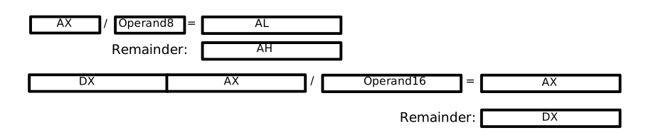
Division (DIV, IDIV)
There are different division operations for unsigned (DIV) and signed (IDIV) numbers.
The explicit operand (given directly after the command) defines the size of the operands.
The dividend must be larger than the divisor. Setting the dividend correctly requires often to set two registers (D register for the upper part, A register for the lower part).
For idiv singed conversion of the operand might be necessary.
The operand can be a register or a memory location but not immediate.
::nasm
DIV BX ; Use DX/AX  as implicit operand. Result is saved in AX. Remainder is saved in DX.
IDIV 0x34 ; Use AX as implicit operand. Result is saved in AL. Remainder is saved in AH.
Unsigned and signed division (div, idiv):
| Size | Registers |
|---|---|
| Byte | al = ax / <src>, remainder in ah |
| Word | ax = dx:ax / <src>, remainder in dx |
| Double-word | eax = edx:eax / <src>, remainder in edx |
| Quad-word | rax = rdx:rax / <src>, remainder in rdx |
Don’t divide by zero!
Affected Flags
- All flags are changed to undefined!
If the result is too big for the register AL resp. AX a interrupt (division error) is caused. If it is not handled the program can crash (undefined behaviour).
Floating Point Instructions
There are special instructions for floating point numbers.
Here are the most important x86-64 floating point instructions shown. They differ from the 32-bit floating point instructions.
Values
- 32-bit: single precision (
floatin C/C++) - 64-bit: double precision (
doublein C/C++)
Single precision instuctions have a s postfix and
double precision instuctions have a d postfix.
Registers
There are 16 XMM registers xmm0 - xmm15 to be used
for floating point instructions.
They are 128 bits (on later processors 256 bits) long.
Data Transfer Commands (movss, movsd)
Copies a value to or from a XMM register.
movss dest, src
movsd dest, src- Only one operand can be memory
- Operands can not be an immediate
Conversion Instructions
| Conversions | float (32-bit) | double (64-bit) | integer (32 bit) |
|---|---|---|---|
| float (32-bit) | - | cvtss2sd | cvtss2si |
| double (64-bit) | cvtsd2ss | - | cvtsd2si |
| integer (32 bit) | cvtsi2ss | cvtsi2sd | - |
Arithmetic Instructions
Addition (addss, addsd)
addss dest, src
addsd dest, src- Destination operands must be an
XMMregister - Source operand can’t be an immediate
Substraction (subss, subsd)
subss dest, src
subsd dest, src- Destination operands must be an
XMMregister - Source operand can’t be an immediate
Multiplication (mulss, mulsd)
mulss dest, src
mulsd dest, src- Destination operands must be an
XMMregister - Source operand can’t be an immediate
Division (divss, divsd)
divss dest, src
divsd dest, src- Destination operands must be an
XMMregister - Source operand can’t be an immediate
Square Root (sqrtss, sqrtsd)
sqrtss dest, src
sqrtsd dest, src- Destination operands must be an
XMMregister - Source operand can’t be an immediate
Control Instructions
There are ordered and unordered floating point compare instructions. Here only the unordered floating point instructions shown.
ucomiss op1, op2
ucomisd op1, op2- Operands are not changed
op1must be anXMMregisterop2may beXMMregister or memory- No immediate operands are allowed
Logical Commands
And, Or and Xor (AND, OR, XOR)
Bit-wise and, or or xor operation.
- The first operand can be a register or a memory address
- The second operand can be a register, a memory address or a constant
- Only one operand can be memory
The first operand is overwritten with the result.
Affected Flags
- Carry and Overflow: are always reset (0)
- Zero and Sign: are set according to the result
Not (NOT)
Bit-wise not (inverse) operation. The operand can be a register or a memory address but not an immediate.
The operand is overwritten with the result.
Affected Flags
- No flags are changed
Rotation Commands
Rotate (ROL, ROR)
Rotate left (ROL) or right (ROR).
Rotates the first operand (memory or register) by the constant 1 (immediate) or by the value given in CL.
ROL 0x34, 1; Rotate by one.
ROR AX, CL; Rotate by value in CL.
Affected Flags
- Overflow:
- For one-bit rotation: Overflow set if MSB is changed by the rotation. Otherwise it’s not set.
- For other cases: Overflow is undefined
- Carry has the value of the bit that was shifted from one end to the other.
Rotate with Carry (RCL, RCR)
Rotate left (RCL) or right (RCR) with carry as MSB.
The first operand (memory or register) is extended with the carry bit as the MSB. It is then rotated by the constant 1 (immediate) or by the value given in CL.
Affected Flags
- Overflow:
- For one-bit rotation: Overflow set if MSB is changed by the rotation. Otherwise it’s not set.
- For other cases: Overflow is undefined
- Carry has the value of the bit that was shifted from one end to the other.
Manipulate the Carry Flag (CLC, STC, CMC)
Clear Carry Flag (CLC): CF = 0.
Set Carry Flag (STC): CF = 1.
Complement Carry Flag (CMC): CF = !CF.
Shift Commands
The shift commands can be used to multiply with or divide by a power of two (2, 5, 8, …).
For a multiplication or a division of a unsigned number the logical shift operators need to be used.
For a multiplication or a division of a signed number the arithmetic shift operators need to be used.
| Direction | Logical | Arithmetic | Notes |
|---|---|---|---|
| Left | shl | sal | Both instructions are identical |
| Right | shr | sar | Instructions work diffently |
- Logical shift (unsigned shift): Spaces filled with zero
- Arithmetic shift (signed shift): Spaces filled so that sign is preserved
- Right: Spaces are filled with sign bit.
- Left: Spaces are filled with zero (doesn’t affect sign), thus same as logical shift
Left Shift Commands (SHL, SAL)
Both left shift operators are functional identical. They muliplicate the operator by 2 or by .
Shifts the given operator (memory or register) left by the constant 1 (immediate) or by the value given in CL.
Affected Flags
- Zero
- Sign
- Offset
- For one-bit shift:
- Carry: For unsigned Operands a set carry flag means overflow
- Overflow: For signed Operands a set overflow flag means overflow
Right Shift Commands (SHR, SAR)
The logical shift right (SHR) divides a unsigned value by 2 or by .
The arithmetic shift right (SHR) divides a unsigned value by 2 or by .
The sign stays unchanged.
The two right shift instructions are not equivalent (not as the two left shift instructions).
The first operand is a memory location or a register. The second operand is the constant 1 or the register CL.
Affected Flags
- CF: For one-bit shifts the carry flag holds the remainder of the division
- ZF
- SF
- (OF)
Jump Commands
Jump commands can be divided by different topics.
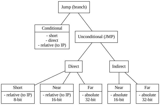
Conditional/Unconditional Jumps
Unconditional jumps are always performed. Conditional jumps are only performed if a check gives an expected result (i.e flags).
Short, Near and Far Jumps
- Short: signed 8-bit distance
- Near: unsigned 16-bit distance
- Far: 32-bit (Segment and Offset)
Direct and Indirect Jumps
- Direct: The target address is given directly after the command
- Indirect: The position is given indirectly by a register or a memory position
Absolute and Relative Jumps
- Absolute jumps: The target address is an absolute address
- Relative jumps: The target address is given relative to the actual position (IP)
The 8086 has following possible jump commands:
Intra- and Inter-Segment Jumps
All jumps change the IP register.
Far jumps also change the CS register.
Intra-Segment Jump
Short- and Near-Jumps change only the IP register. The target is always inside the actual code segment (CS).
Near Jump
- Direct Near-Jumps are always relative to IP.
- Indirect Near-Jumps are always absolute to the actual code segment.
Short Jump
Short Jumps are always relative to IP.
Inter-Segment Jump
Far jumps change CS and IP.
All far jumps are absolute.
Unconditional Jumps (JMP)
- 8-bit displacement is added to IP as signed number:
JMP displ8
- 16-bit displacement is added to IP as unsigned number:
JMP displ16
- The constant is the absolute 32-bit FAR-addressed:
JMP const32
- IP is loaded with the value of the register:
JMP reg16
- IP is loaded with the value given by the memory position:
JMP mem16
- CS and IP are loaded with the value at the memory position:
JMP mem32
The unconditional jump are not limited in range.
Conditional Jumps
Conditional jumps check one or more flags and jump to a given address if a condition is met.
Before the jump can be performed the flags need to be set by a logical or arithmetic command.
Alternatively the commands CMP and TEST can be used.
Conditional jumps can be divided into following groups:
- Arithmetic jumps: The jump depends on size difference of two operands. The two operands have to be compared in advance. One or more flags have to be checked.
- Flag oriented jumps: A jump is performed if one given flag is set or deleted.
Arithmetic Jumps
The jump is performed if the size relation between two given operands is as expected.
The relation is expressed differently for signed and unsigned operands:
| Relation | unsigned | signed |
|---|---|---|
| equal | equal | |
| below | less | |
| above | greater |
Arithmetic “unsigned” Jumps
| Relation | Command | Explanation | Condition |
|---|---|---|---|
JE | Jump if equal | ZF 1 | |
JNE | Jump if not equal | ZF 0 | |
JB | Jump if below | CF 1 | |
JNAE | Jump if not above or equal | CF 1 | |
JAE | Jump if above or equal | CF 0 | |
JNB | Jump if not below | CF 0 | |
JBE | Jump if below or equal | CF 1 or ZF 1 | |
JNA | Jump if not above | CF 1 or ZF 1 | |
JA | Jump if above | CF 0 and ZF 0 | |
JNBE | Jump if not below or equal | CF 0 and ZF 0 |
Arithmetic “signed” Jumps
| Relation | Command | Explanation | Condition |
|---|---|---|---|
JE | Jump if equal | ZF 1 | |
JNE | Jump if not equal | ZF 0 | |
JL | Jump if less | OF SF | |
JNGE | Jump if not greater or equal | OF SF | |
JGE | Jump if greater or equal | OF SF | |
JNL | Jump if not less | OF SF | |
JLE | Jump if less or equal | OF SF or ZF 1 | |
JNG | Jump if not greater | OF SF or ZF 1 | |
JG | Jump if greater | OF SF and ZF 0 | |
JNLE | Jump if not less or equal | OF SF and ZF 0 |
Flag oriented Jumps
| Command | Explanation | Condition |
|---|---|---|
JZ | Jump if zero | ZF 1 |
JNZ | Jump if not zero | ZF 0 |
JC | Jump if carry | CF 1 |
JNC | Jump if no carry | CF 0 |
JS | Jump if sign | SF 1 |
JNS | Jump if no sign | SF 0 |
JO | Jump if overflow | OF 1 |
JNO | Jump if no overflow | OF 0 |
JP | Jump if parity | PF 1 |
JNP | Jump if no parity | PF 0 |
JPE | Jump if parity even | PF 1 |
JPO | Jump if parity odd | PF 0 |
Comparing Commands (CMP, TEST)
Since the different jump commands depend on flags set or not there are special commands that only affect the flags.
CMPis a subtraction of the operands (8-bit or 16-bit) but it only changes the flags. The result is not written anywhere.TESTis a AND operation of the operands (8-bit or 16-bit) that only changes the flags. The result is not written anywhere.
Both commands accept a register or a memory location as first operand and a register, a memory location or a constant (immediate) as second operator.
Only one memory operand is allowed.
The operands need to be of the same size.
Loop Commands (LOOPx, JCXZ)
All loop commands accept an displacement operator (8-bit).
None of the loop commands affects any flags!
Loop (LOOP)
Decrements RCX by one (1). If RCX is not zero (RCX 0) it performs the jump.
Loop while equal and Loop while zero (LOOPE, LOOPZ)
LOOPE and LOOPZ are different mnemonics for the same command.
Decrements CX by one (1). Performs the jump if if Zero Flag is set and CX is not zero (0).
Jump if: ZF 1 and CX 0
Loop while not equal and Loop while not zero (LOOPNE, LOOPNZ)
LOOPNE and LOOPNZ are different mnemonics for the same command.
Decrements CX by one (1). Performs the jump if if Zero Flag is not set and CX is not zero (0).
Jump if: ZF 0 and CX 0
Jump if CX zero (JCXZ)
Performs the jump if CX is zero.
Jump if: CX 0
Stack and Function calls
The stack on x86 is always addressed by the Stack Segment (SS).
On 80186 stack operations are word aligned (16-bit). So PUSH
decrements SP by 2 and POP increments SP by 2.
On x86-64 stack operations are quad-wor (64-bit) aligned.
So PUSH decrements RSP by 8 and POP increments RSP by 8.
It’s possible to use pop and push instructions for operands smaller than 64-bits. But it’s not recomended.
The stack on x86 grow downwards (reverse in memory).
RSP points to the last written item. It is the top of the stack (smallest address on stack).
Push and Pop (PUSH, PUSHF, PUSHA, POP, POPF, POPA)
The different push and pop commands save/restore 16-bit words to/from the stack.
PUSH
PUSH can be called with all registers as as operands or a memory
operand. Immediate addressing is not possible with PUSH.
The registers that can be pushed are: AX, BX, CX, DX, SP, BP, SI, DI, ES, SS, DS and CS.
POP
POP can use the same operands as PUSH with the exception of CS. Memory operands are also possible.
The registers that can be poped are: AX, BX, CX, DX, SP, BP, SI, DI, ES, SS and DS.
PUSHA and POPA
With the commands PUSHA and POPA (introduced with 80186) the 8 working registers are pushed to the stack and
poped in the reversed order:
AX, CX, DX, BX, SP+, BP, SI, DI
SP+ is the SP before the first push to the stack. With POPA SP is not poped. Is is just decremented (by 2) at
the end of all the pop operations.
PUSHF and POPF
PUSHF and POPF push and pop the flag register to/from the stack.
Examples
PUSH result   ; variable result
PUSH [BX+7]   ; memory word at address [BX+7]
PUSH tab[SI]  ; memory word at address tab[SI]
POP AX        ; value from stack to AX
CALL and RET
CALL stores the return address (address of the instruction after CALL) on the stack, increments SP (by 2)
and calls the function.
RET returns from the function by loading the stored address in to IP and decrements SP (by 2).
Defining a Function
Functions need to be placed in the code segment.
In NASM a function is defined as follows:
my_func:; code of the function...
retFor calling the function:
call far my_funcThe pseudo commands PROC and ENDP` (as in MASM/TASM) are not supported by NASM.
Function definitions can not be nested.
Function Prologue
At the beginning of each function some registers have to be saved. This code is called function prologue.
The usual tasks in a function prologue are:
- Save old BP (push it on the stack).
- Assign SP to BP (PB = SP). So the BP points the the old BP.
- Save register contents to stack. So the registers can be used in the function.
- Allocate memory on stack for use in function.
The the actual code of the function can run.
Before the function ends it has to undo most of the things that were done in the prologue (i.e restoring registers, adjusting SP…). This code is called function epilogue.
String Operations
The x86 architecture contains some commands that can be executed on consecutive memory location (strings, arrays…).
This commands are powerful but not so easy to understand.
Commands
Mostly SI is used for addressing the source operator and DI is used for addressing the destination operator. Hence the names. For some commands the accumulator (AL/AX) is used as operator. SI is DS-relative by default. But the segment can be overridden. DI is ES-relative by default. The segment can not be overridden.
| Command | Purpose |
|---|---|
MOVSx | Move (copy) data addressed by SI to position addressed by DI. |
STOSx | Load data from accumulator to position addressed by DI. |
LODSx | Load data addressed by SI into accumulator. |
CMPSx | Compare data addressed by SI with data addressed by DI. Flags are set according to result of [SI] - [DI]. |
SCASx | Compare data from accumulator with data addressed by DI. Flags are set according to result of accumulator - [DI]. |
In the commands listed above x can be B for operation on bytes or W for operation on words (16-bit).
Processors 80186 and newer have also the commands: INS and OUTS for string input and output from/to ports.
Direction
The direction of the string commands can be controlled by the direction flag:
CLD: Clear direction flag. Index registers are incremented.STD: Set direction flag. Index registers are decremented.
Repeat Prefix
REP: Repeat the string command as long as CX 0. Decrement CX in each iteration.REPE: Repeat while operands are equal.REPZ: Repeat while zero (ZF = 1).REPNE: Repeat while operands are not equal.REPNZ: Repeat while not zero (ZF = 0).
There is now practical use for
LODSxwithREP.