My Notes for the System Construction Course at ETH
Minos on Raspberry PI 2 (Case Study 1)
ARM A7
The ARM Architecture is not the same thing as the ARM Processor-Families
Documentation
There is a lot of good documentation for the ARM processors available. But it’s difficult to find the right documents.
| Document | Main Content |
|---|---|
| ARM Architecture Reference Manual (ARMv7-AR, ARM ARM) | Possibility of implementing the processor. For compilers and tools. Partly used for system programming |
| ARM Technical System Reference (ARM Cortex-A7MPCore Family) | Particular Implementation. Some redundant information to ARM ARM. |
| System On Chip Implementation Manual (BCM 2835) | How the core is embedded on the chip with peripherals. Address map. Peripheral information. |
6 Kinds Of Instructions
- Data Processing
- Branch Instructions
- Status Register Transfer
- Load and Store (RISC)
- Generic Coprocessor Instructions
- Exception Generation
- Load-/Store: No memory operands (not as x86)
- Load: from memory to register
- Store: from register to memory
- Multiple-Data-Transfer commands (
stmdb sp!,{fp,lr},!: Write-Back) - Link Register:
bl: Branch-and-Link (stores PC in link register) - PC-Relative Addressing: Loading large constants (that have no space in instruction encoding) form code
Execution Modes
- 7 Modes
- for exception handling
- Processor starts in supervisor mode
- Registers are shadowed (banked) in different modes
- System Mode: privileged but same registers as user mode
| Privilege Level | Mode | Description/Cause | Exception/Normal Execution |
|---|---|---|---|
| privileged | Supervisor | Reset / Software Interrupt | exception |
| privileged | FIQ | Fast Interrupt | exception |
| privileged | IRQ | Normal Interrupt | exception |
| privileged | Abort | Memory Access Violation | exception |
| privileged | Undef | Undefined Instruction | exception |
| privileged | System | Privileged Mode with same registers as in User Mode | normal execution |
| unprivileged | User | Regular Application Mode | normal execution |
Special Registers
- R15: PC (Program Counter)
- R14: LR (Return address for procedure)
- R13: SP (‘top’ of the stack)
- R12: FP (by convention, stored SP before procedure call)
- CPSR (Processor Status Register)
- Mode Bits
- IRQ Disable
- Condition Flags
- …
Typical Procedure Call
-
Caller
- Pushes params
BL #address: Stores PC of next instruction in LR
-
Callee
- Save LR and FP on stack:
stmdb sp!, {fp, lr} - Set new FP:
mov fp, sp - Execute procedure content
- Reset stack pointer:
mov lr, sp - Restore FP and jump back to caller address:
ldmia sp!, {fp, pc}
- Save LR and FP on stack:
-
Caller
- Clean up parameters from stack:
add sp,sp, #n
- Clean up parameters from stack:
Exceptions
- Interrupt: asynchronous event triggered by a device signal
- Trap / Syscall: intentional exception
- Fault: error condition that a handler might be able to correct
- Abort: error condition that cannot be corrected
Misc
- FIRQ is about having more stacked registers
- Return Link type: Different sizes because of pipe-line
Raspberry PI 2
- Quad Core
- 1 GB RAM
- 40 Pin GPIO, …
- UART, SPI, USB, Ethernet, …
- Powered from MicroUSB
Booting
- Kernel is copied to address:
0x8000hand branches there (instead to0x00) - MMU is disabled
- Only one core is running
MMU
- Memory translation is complicated due to two different MMU’s
- ARM’s memory mapped registers start from
0x3f000000, opposed to0x7e000000in BMC manual
GPIO
- Some GPIO Registers need Read-Modify-Write (i.e GPFSELn)
- Other Registers support setting or clearing single bits:
- i.e Set GPIO Pin: GPSETn
- i.e Clear GPIO Pin: GPCLRn
Minos and Oberon
History of Oberon
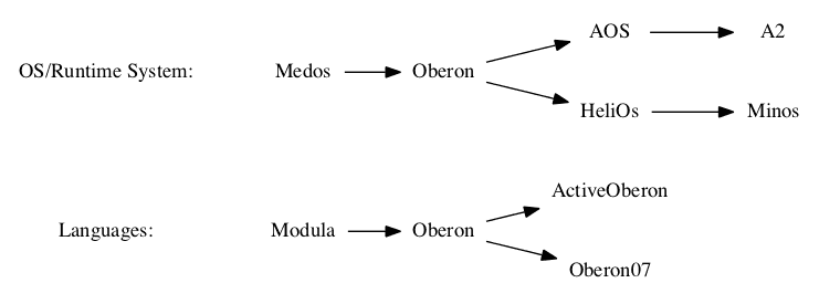
Oberon
- Modules can be compiled separately
- Strongly typed
- Static type checking at compile time
- Run-time support for type guards / tests
- High Level (minimal Assembler code)
- Special low level functions in
SYSTEMpseudo module (compiler directives)
Oberon07
- Minimal
- No type
OBJECT*no member functions (methods)
Language Constructs
Program Units
MODULEPROCEDURE- Value,
VAR(in-out) andCONSTparameters
- Value,
Data Types
BOOLEAN,CHAR,SHORTINT,INTEGER,LONGINT,HUGEINT,REAL,LONGREAL,SET,ADDRESS,SIZE
Structured Types
ARRAY,POINTER TO ARRAYRECORD(with type extension),POINTER TO RECORD
Control Structures
IF
IF a = 0 THEN
    (* statement sequence *)
END;
WHILE
WHILE x<n DO
    (* statement sequence *)
END;
REPEAT
REPEAT
    (* statement sequence *)
UNTIL x=n;
FOR
FOR i := 0 TO 100 DO
    (* statement seq *)
END;
Built-in Functions
Increment and decrement
INC(x);
DEC(x);
INC(x,n);
DEC(x,n);
Sets
INCL(set, element);
EXCL(set, element);
Assert and Halt
ASSERT(b<0);
HALT(100);
Allocation
NEW(x, ...);Shifts
ASH(x,y);
LSH(x,y);
ROT(x,y);
Conversion
SHORT(x);
LONG(x);
ORD(ch);
CHR(i);
ENTIER(r);
Arrays
LEN(x);
LEN(x,y);
DIM(t);
Misc
ABS(x);
MAX(type);
MIN(type);
ODD(i);
CAP(c);
Addresses and Sizes
ADDRESS OF x;
ADDRESSOF(x);
SIZE OF t;
SIZEOF(t);
Modules
PROCEDURE Write* ...: Exported (*)- Module body is executed first and only once
- Module can be loaded only once (keeps state, can be unloaded)
- Procedures without params can be executed as commands
- Comments:
(* ... *) - Special Type:
SETcontains ints up to CPU bit size: i.e 1..32 ({12, 5}) SYSTEMPseudo Module- Unsafe!
- Memory Access
SYSTEM.BYTE: raw binary data (with length and bound checks)- Type Casts: can be unsafe!
- Procedure Flags:
INTERRUPT: for ISR’sPCOFFSET=k: offset for returning from ISR
- Unsafe Pointer: can write to memory address
Pseudo Module SYSTEM
Direct Memory Access Functions
SYSTEM.PUT (a, x);
SYSTEM.GET (a, x);
SYSTEM.PUT8|16|32|64(a, x);
x := SYSTEM.GET8|16|32|64(a);
SYSTEM.MOVE(src, dest, length);
Data Type
SYSTEM.BYTEType Cast
b := SYSTEM.VAL(a, t);Example of Low-Level access
IMPORT SYSTEM;

PROCEDURE LetThereBeLight;
CONST GPSET0 = 03F20001CH;
BEGIN
    SYSTEM.PUT(GPSET0, {21});
END LetThereBeLight;SYSTEM: ARM Specific
Register Access
SYSTEM.SP();
SYSTEM.FP();
SYSTEM.LNK();

SYSTEM.SETSP(x);
SYSTEM.SETFP(x);
SYSTEM.SETLR(x);

SYSTEM.LDPSR(b,x);
SYSTEM.STPSR(b,x);
SYSTEM.LDCPR(a,b,c);
SYSTEM.STCPR(a,b,c);
SYSTEM.FLUSH(x);
Floating Point
SYSTEM.NULL(x);
SYSTEM.MULD(a,b,c);
Interrupt Procedures
PROCEDURE Handler {INTERRUPT, PCOFFSET=k};
BEGIN (* k is the offset to the next instruction
         cf. table of exceptions *)
END Handler;
Special Flags and Features
Procedure without activation frame
PROCEDURE {NOTAG}Procedure that is linked to the beginning of a kernel
PROCEDURE {INITIAL}Inline assembler block
CODE ... ENDAlignment of a symbol (i. e variable)
symbol {ALIGNED(32)}Pinning of a symbol
symbol {FIXED(0x8000))Unsafe pointer that is assignment compatible with type ADDRESS
POINTER {UNSAFE} TO ...Symbol that is invisible to a Garbage Collector
symbol {UNTRACED}Type Declarations
TYPE

Device* = POINTER TO DeviceDesc;  (* Pointer to record (reference type)*)
DeviceDesc* = RECORD              (* Record: Value type *)
    id*: INTEGER;
    Open*: PROCEDURE(dev: Device);
    Close*: PROCEDURE(dev: Device);
    next*: Device;
END;

(* Procedure type with signature *)
TrapHandler* = PROCEDURE(type, addr, fp: INTEGER; VAR res: INTEGER);

NumberType* = REAL; (* Type alias *)

DeviceName* ARRAY DeviceNameLength OF CHAR; (* Array Type *)

Data* POINTER TO ARRAY OF CHAR; (* Dynamic array type *)
Inheritance
Task* = POINTER TO TaskDesc;
TaskDesc* = RECORD
    task task task
    task task
    proc:PROCEDURE(me:Task); (* This procedure is executed in the task *)
    next: Task;              (* The next task in the list of tasks *)
END;

PeriodicTask* = POINTER TO PeriodicTaskDesc;
PeriodicTaskDesc* = RECORD (TaskDesc) (* inherits TaskDesc *)
    priority: LONGINT; (* The priority determines the execution order *)
    interval: LONGINT; (* The task is executed every "interval" msecs *)
END;
Type Test
IF task IS PeriodicTask THEN ... END;Type Guard (cast)
IF task(PeriodicTask).priority = 1 THEN ... END;Type Test and Guard
WITH task: PeriodicTask DO ... END;Run-time Support for Inheritance
- RTTI is supported
- Each type gets an unique type descriptor (
LONGINT) - The variables contain an array of up to 3 tags
- The tags point to the type descriptors
- Inheritance level is restricted to 3
Module Loading and Commands
- Modules are loaded on demand (first use)
- Statically linked modules are loaded at boot-time
- Exported Procedures without parameters act as commands
- Modification of modules needs reloading
- Unloading possible, if no other loaded module (static or dynamic) depends on it
- If a command of a not loaded module is executed the module is loaded first
Compilation and Linking
- A module (.mod) is compiled to an executable file / object file (.arm) and a symbol file (.smb)
- The executable file contains a fingerprint
- The linker adds fingerprint to dependent object files (fix-up)
Object File Format
Compiler flags:
Compiler.Compile -b=ARM --objectFile=Minos- The object file is very compact
- Key: Fingerprint
- Fix-ups → Fix-up-root (relocation table) linked list to fix-ups
- Downsides:
- Module file is limited
- Not very maintainable
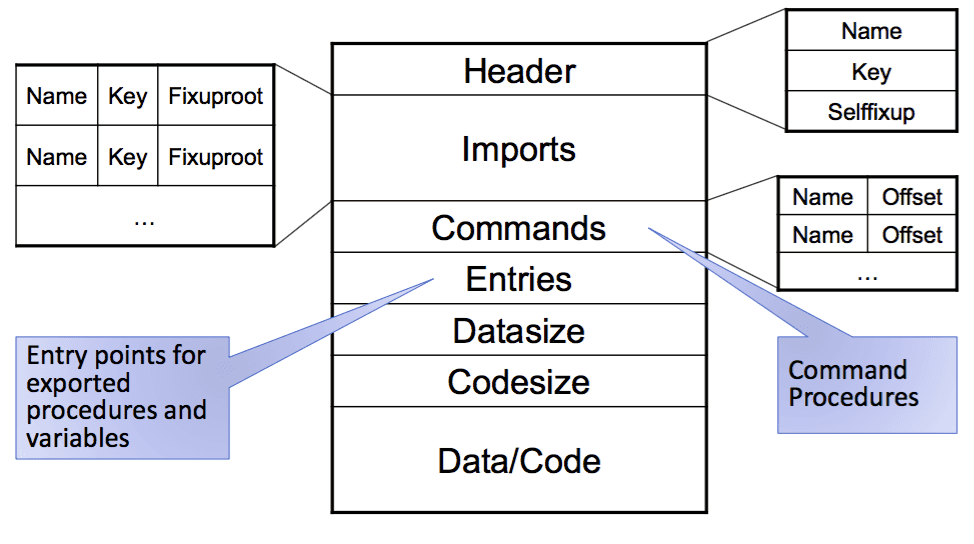
This image is taken from the lecture slides provided by Felix Friedrich
Boot-file
- Linked Modules of Kernel files (hierarchy)
- Predefined loading address and entry point (0x8000 for RPI2)
Boot-Linking command in host system
MinosLinker.Link minimalinit.img 108000H kernel.img OFSRamVolumes SerialLog Minos ~- Image header:
minimalinit.img - Start address:
108000H - Image file name:
kernel.img - Object file names (compiled):
OFSRamVolumes SerialLog Minos ~
Minos Kernel
System Start-up
-
Firmware (RPI2, GPU)
- Initialise HW
- Copy boot image to RAM
- Jump to boot image (initializer)
-
Initializer
- Set stack registers for all processor modes
- Setup free heap and module list
- Initialise MMU and page table
- Setup interrupt handler and vectors
- Start timer and enable interrupts
- Initializer UARTs, RAM disks, …
- Enter scheduling loop on OS
The Minos Kernel is modular:
- Minos: Command interpreter and scheduler
- Modules: Module loader, dynamic linker
- File System: RamVolumes, OFS, …
- Kernel: Memory management, device drivers
- I/O: Kernel logging, …
- Run-time: Memory allocation (heaps), FPU emulation, …
…
Initialisation of Interrupts
- Set handlers of IRQ’s
- Write handlers for needed interrupts
- Put jumps to handlers into interrupt table
- Enable IRQ’s
Usually Interrupts need to be configured in 3 parts:
- CPU (enable, masking…)
- Interrupt Controller
- Device
The RPI2 has 3 memory-mapped IRQ registers (32-bit):
- Pending Bits indicate which interrupts are pending
- Need to be checked in the IRQ Trap Handler (1st level handler)
- Call IRQ Handler (2nd level) depending on pending bits
Task Scheduling (Minos)
3 Task types:
- High Priority (every 5 ms)
- Low Priority (every 20 ms)
- Background tasks
Preemption:
- High priority tasks preempt low priority and background tasks
- Low priority tasks preempt only low priority tasks
- Background tasks don’t preempt any tasks
Task Descriptors for
- Synchronous (periodic) tasks
- Asynchronous (background) tasks
Stack (Minos)
- One stack for all processes
- Every task needs to run to completion
- Preemption is possible
- Preempting task needs to be completed before returning
Scheduler (Minos)
Recursive interrupt procedure
- Prolog: Interrupts masked
- Scheduling: Interrupts allowed
- Epilogue: Interrupts masked
Scheduler procedure must be reentrant
- Register values on stack
- Private variables
Assumptions for scheduler
- Linked list stores tasks sorted by period and priority
- Tasks run to completion within given period
Serial Communication
- Directionally
- Simplex
- Half duplex
- Full duplex
- Synchrony
- Synchronous
- Asynchronous
Examples:
- RS-232
- RS-458
- SPI (SSP, Microwire)
- IC
- 1-Wire
- USB
SPI
- Very simple
- 4 Wires:
- SCLK: Serial bit-rate Clock
- MOSI: Master data Output, Slave data Input
- MISO: Master data Input, Slave data Output
- SS: Slave Select
- Configurations:
- Single slave mode: 1 Master, 1 Slave
- multiple slave mode: 1 Master, N Slaves
- Synchronous bidirectional data transfer
- Data transfer initiated by master
- Bandwidth some KBits/s up to several MBits/s
- Simple implementation in software possible (bit-banging)
- Master and Slave have shift registers for data (in and output)
- During communication data ‘circles around’ between the two shift registers
Communication
- Master pulls SS to low
- Master pushed data out of shift register
- Slave pushes data out of shift register at the same time
- Sampling happens at SCLK
- To finish communication master stops SCLK
- No acknowledgment mechanism
- No device interrupts
Setup
- Polarity (SCLK):
- 0: Sampling happens on rising SCLK edge
- 1: Sampling happens on falling SCLK edge
- Phase (SCLK):
- 0: Rising SCLK edge in the middle of data
- 1: Rising SCLK edge on beginning of data
UART
- Serial transmission (least significant bit first)
- Configurable
- Number of data bits: 5, 6, 7, 8
- Parity: odd, even, none
- Stop-bits: 1, 1.5, 2
- Transfer rate (bits per second): 75, 110, 300, …, 115200
- Flow control exists in some implementations
A2 (Case Study 2)
Intel x86
- Shared Memory (for all processors)
- Symmetrical Multiple Processors (SMP)
Resources (x86 compatible HW)
- SDM: Intel® 64 and IA-32 Architectures Software Developer’s Manual (4000 p., 3 volumes)
- Architecture
- Instruction Set Reference
- System Programming Guide
- MP Spec: Intel Multiprocessor Specification, version 1.4 (100 p.)
- ACPI Spec: Advanced Configuration and Power Interface Specification (1000 p.)
- PCI Spec: PCI Local Bus Specification Rev. 2.2 (322 p.)
Interrupt System (x86)
- External IRQ’s (asynchronous)
- I/O Devices
- Timer
- Inter-processor interrupts
- Software IRQ’s (synchronous)
- Traps/Syscall: special instructions
- Processor exceptions (synchronous)
- Faults (restartable): i.e page fault
- Aborts (Fatal): i.e machine check
APIC
-
Each CPU has local APIC (local interrupts)
-
I/O APIC for all CPU’s (external interrupts)
-
Messages to processors
- Start Processor: Activation and Initialisation of individual processors
- Halt Processor: Deactivation of individual processors
- Halt Process, schedule new process: Interrupt in order to transfer control to scheduler
-
Local timers
- Periodical interrupts
MultiProcessor Specification
- Standard by Intel (MP Spec 1.4)
- Hardware Specification
- Memory Map
- APIC
- Interrupt Modes
- MP Configuration Table
- Processor, Bus, I/O APIC
- Table address searched via “floating pointer structure”
Exception Numbers
| Vector # | Description | Source |
|---|---|---|
| 0 | Div error | div / idiv instruction |
| 1 | Debug | Code / data reference |
| 2 | NMI | Non maskable external IRQ |
| 3 | Breakpoint | int 3 instruction |
| 4 – 19 | Other processor exceptions | E.g. page fault etc. |
| 20-31 | reserved | |
| 32-255 | Maskable Interrupts | External Interrupts from INTR pin INT n instruction |
Configuring APIC
- Local Vector Table (for local interrupt sources)
- Vector Number, Trigger Mode, Status, Interrupt Vector Mask
- Timer Mode (one shot / periodic)
- Command Register: Inter Processor Interrupt with
- vector number,
- delivery mode: fixed, nmi, init, startup (..)
- logical / physical destination (including self and broadcasts with / without self
PCI Local Bus
- Connect Peripheral Components
- Standardised Configuration Address Space for all PCI Devices
- Interrupt Routing Configuration
Access mechanism
- PCI BIOS: offers functionality such as “find device by classcode”. Presence determined by floating data structure in BIOS ROM
- Addressable via in / out instructions operating on separate I/O memory address space
- PCI Express now Memory Mapped I/O
Active Oberon Language
Locks vs. Monitors
- Lock based
- shared data
- protected from concurrent access by locks
- Monitor based
- locks code (methods) that access shared data
- No direct locking of data structures needed
Threads vs. Active Objects
- Threads
- Concurrently running code
- Active Objects
- Objects that contain threads
- Threads in form of Monitors
Object Model (Active Oberon)
-
EXCLUSIVE: Protection (mutual exclusion)- Methods tagged
EXCLUSIVErun under mutual exclusion - As
synchronizedin Java
- Methods tagged
-
AWAIT: Synchronisation- Wait until condition of
AWAITbecomes true
- Wait until condition of
-
ACTIVE: Parallelism- Body marked
ACTIVEexecuted as thread for each instance
- Body marked
Signal-Wait Implementations
- Signal-and-Continue
- Java uses this
- Race conditions can occur
- Signal-and-Exit
- Active Oberon uses this
- Can be achieved in Java by looping on wait condition
Active Oberon:
Semaphore = OBJECT
    number := 1: LONGINT;

    PROCEDURE enter;
    BEGIN{EXCLUSIVE}
        AWAIT number > 0;
        DEC(number)
    END enter;

    PROCEDURE exit;
    BEGIN{EXCLUSIVE}
        INC(number)
    END exit;

END Semaphore;
Equivalent Java code:
class Semaphore{
    int number = 1;
    synchronized void enter() {
        while (number <= 0)  // while needed!
            try { wait();}
            catch (InterruptedException e) { };
        number--;
    }


    synchronized void exit() {
        number++;
        if (number > 0)
            notify();  /* notifyAll() needed if different threads
                          evaluate different conditions */
    }
}
Monitors in Active Oberon
- No notify() (or notifyAll()): Every
EXCLUSIVEprocedure triggers reevaluation ofAWAITwhen it returns - Downsides of Monitors:
- Wasting of processor time on looping on ‘locks’
- Ordering can not be influenced
Active Object System (A2)
Modular Kernel Structure
- Cover: Kernel
- Activity Scheduler: Objects
- Module Loader (Memory Management): Modules, Heaps
- Hardware Abstraction: Machine
Atomic Operations (HW Support)
The supported operations are typically a lot slower than simple read and write operations.
Intel (x86)
From AMD64 Architecture Programmer’s Manual:
CMPXCHG mem, reg
“compares the value in Register A with the value in a memory location If the two values are equal, the instruction copies the value in the second operand to the first operand and sets the ZF flag in the flag registers to 1. Otherwise it copies the value in the first operand to A register and clears ZF flag to 0”
- Lock Prefix
“The lock prefix causes certain kinds of memory read-modify- write instructions to occur atomically”
ARM
From ARM Architecture Reference Manual:
LDREX <rd>, <rn>
“Loads a register from memory and if the address has the shared memory attribute, mark the physical address as exclusive access for the executing processor in a shared monitor”
STREX <rd>, <rm>, <rn>
“performs a conditional store to memory. The store only occurs if the executing processor has exclusive access to the memory addressed”
Overview
Some typical instructions for atomic operations and implementation examples.
- Test-And-Set (TAS)
TSL register, flag(Motorola 68000)
- Compare-And-Swap (CAS)
LOCK CMPXCHG(Intel x86)CASA(Sparc)
- Load Linked / Store Conditional
LDREX/STREX(ARM)LL/SC(MIPS)
These hardware instructions are often much slower than simple read and write. Caches can’t be exploited (direct access to memory)!
- Compare-And-Swap is the most universal instruction
Compare-And-Swap (CAS)
Atomic operation implemented in processor.
Compares memory location with an value. If it’s same a new (given) value is written at the memory address. Returns the previous value at memory position in any case.
int CAS(int* a, int old, int new)- If value
oldis at memory location ofa: safenewata - Return previous value at
ain any case
Implementation of a spinal using CAS
(* Initialisation *)
Init(lock)
    lock = 0;

(* Acquire Lock *)
Acquire (var lock: word)
    repeat
        res := CAS(lock, 0, 1);
    until res = 0;

(* Release Lock *)
Release (var lock: word)
    CAS(lock, 1, 0); (* atomicy not needed but visibility/ordering *)
Boot Procedure (A2)
- Start BIOS Firmware
- Load A2 Boot-file
- Initialise modules
- Module Machine
- Module Heaps
- …
- Module Objects
- Setup scheduler and self process
- Module Kernel
- Start all processors
- …
- Module Boot-console
- read configuration and execute boot commands
This all happens on the Boot Processor (BP)
Processor Startup
- Start processor P (Boot-processor)
- Setup boot program (
Machine.InitProcessors) - Enter processor IDs into table (
Machine.InitBootPage) - Send startup message to P via APIC (
Machine.ParseMPConfig) - Wait with timeout on started flag by P (
Machine.StartProcessor)
- Setup boot program (
- Boot program (For each processor)
- Set 32-bit run-time environment (
Machine.EnterMP) - Initializer control registers, memory management, interrupt handling, APIC
- Set started flag (
Machine.StartMP) - Setup Scheduler (
Objects.Start) - Boot-processor proceeds with boot console
- Set 32-bit run-time environment (
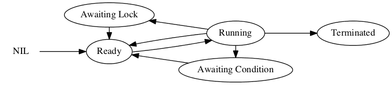
A2 Activities States
- Ready: ready to be scheduled
- Running: currently scheduled
- Waiting
- Condition (
AWAIT): waiting until condition is met - Lock (
EXCLUSIVE): waiting to enter monitor
- Condition (
- Terminated: Activity finished executing
Java doesn’t make difference between waiting on a condition or a lock.
Run-Time Data Structures
- Running Array/List
- One entry for each processor
- Index: id of processor
- Object header (for each object)
- List of conditions (for each condition)
- List of locks (for each monitor)
- Ready Queues/Heap
- Idle
- Low
- Medium
- High
- Garbage Collector (GC)
- Real-time (RT)
- Interrupt Array (first level IRQ’s)
- Index: IRQ number
Stack Management
- Virtual addressing
- Allocation in page units
- Page fault for detecting stack overflow
- Deallocate process stack via garbage collector (in process finalizer)
- Life cycle:
- CreateProcess: Allocate first frame
- Page fault: Allocate another frame
- Finalize: Deallocate all frames
Active Oberon has one shared memory for all processes!
- One Heap for all processes (no heavy-weight processes)
- Each process has own stack
- All processes share same address space
- 8’000 processes can be allocated
- 4 GB address space
- 4 kB pages
- 1024 pages per process
- ↳ ~ 8’000 processes
Context Switch
- Synchronous
- Explicit
- A process terminates
Yield
- Implicit
- Mutual exclusion
AWAIT
- Explicit
- Asynchronous
- Preemption
- Priority handling
- Time-slicing
- Preemption
Coroutines (Synchronous)
- Synchronous context switch
- Context switch:
- Replace SP and FP of old process with SP and FP of new process
- PC needs also to be adjusted
- Stack can be used to identify process
Asynchronous Context Switch
- Needs to save much more than for a synchronous context switch
- Save all registers (copy state)
Synchronisation
Object Locking
-
Object descriptors (added by system): Object with mutual exclusion contain additional fields
headerLock: BOOLEAN;lockedBy: Process;awaitingLock: ProcessQueue;awaitingCondition: ProcessQueue;
-
Locking (Procedure
Lock)- Try to acquire object
- when we have it, we can change the data structure
- if we don’t have it (we need to give up control)
- Synchronous switching to an other process
SelectandSwitchTo
- Try to acquire object
-
Unlocking (Procedure
Unlock)- When giving up a lock all conditions need to be evaluated again (signal-and-exit)
- Otherwise the opposite of locking
-
Wait Conditions (
AWAIT)- Internally boxed into a procedure (
PROCEDURE $Condition(fp: ADDRESS): BOOLEAN;) - Stack frame is needed in condition: FP
AWAITcode: put condition on await queue
- Internally boxed into a procedure (
Side-effects in
AWAITconditions are dangerous!
Priority Inversion
Example:
- 3 processes, 1 shared resource
- P1: low
- P2: high
- P3: medium
- R: shared resource
- P1 locks R
- P2 tries to lock R (needs to wait)
- P3 preempts P1
- P1 can’t release R
- P2 can’t continue until P1 releases R
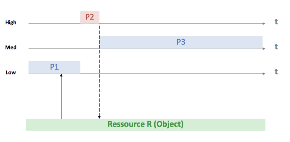
This image is taken from the lecture slides provided by Felix Friedrich
Priority Inheritance
- One possibility to cope with priority inversion
- The priority of each process holding a lock to a resource is increased to the highest priority of all waiting processes (for the lock)
- Need to walk the graph of locks and processes
Lock-Free Programming
Problems with Locks
- Deadlocks
- Livelocks
- Starvation
Different Goals
- Parallelism
- Progress Guarantees
- Reentrancy
- Granularity
- Fault Tolerance
Definition of Lock-Freedom
At least one algorithm (process, thread) makes progress, even if others run concurrently, fail or get suspended.
- Starvation can still happen
Definition of Wait-Freedom
Each algorithm makes eventually progress.
- Implies freedom from starvation
Progress Conditions:
| Blocking | Non-Blocking | |
|---|---|---|
| Someone make progress | Deadlock-free | Lock-free |
| Everyone makes progress | Starvation-free | Wait-free |
- Lock-free programming basically makes loop around CAS
- Overflows (i.e INTEGER) is critical
A2
Goals
- Lock Freedom
- Progress Guarantees
- Reentrant Algorithms
- Portability
- Hardware Independence
- Simplicity, Maintenance
Guiding Principles
- Use implicit cooperative multitasking
- no virtual memory
- possible optmizations are limited
- Co-design of OS, Compiler and Programming Language
Lock-Free Kernel
- Needs lock-free queue
- Compare-And-Swap (CAS) is implemented wait-free in hardware
Memory Model for Lock-Free Active Oberon
- Data shared between two or more activities at the same time has to be either
- protected by
EXCLUSIVEblocks or - read or modified using the compare-and-swap operation
- protected by
- Changed shared data is visible to other activities after
- leaving an
EXCLUSIVEblock or - executing a compare-and-swap operation
- leaving an
CASis an operation in the programming language
Declaration:
PROCEDURE CAS(variable, old, new: BaseType): BaseType- Performance of
CAS- On the HW level
CAStriggers a memory barrier - Performance suffers with increasing number of contenders (contention)
- On the HW level
ABA Problem
The ABA Problem occurs when one thread fails to recognise that a memory location was modified temporarily by another thread and therefore erroneously assumes that the overall state has not been changed.
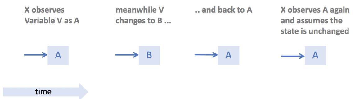
This image is taken from the lecture slides provided by Felix Friedrich
- The ABA Problem makes it difficult to reuse nodes in a stack structure
- Possible to allocate always new memory, but it’s expensive
- Solution: hazard pointers
Hazard Pointers
- ABA Problem because of reuse of pointers
- Pointer P that has been read by one thread X but not yet written by same thread
- Pointer P is written by other thread Y between reading and writing of first thread X
- [Hazard pointers](https://en.wikipedia.org/wiki/Hazard_pointer:
- Each lock-free data structure has an array (hazard array) of the size of number of threads (n=number of threads)
- Before X reads P, it marks it hazardous in the hazard array of data structure (e.g. the stack)
- When finished (after the
CAS), process X removes P from the hazard array - Before a process Y tries to reuse P, it checks all entries of the hazard array
- Hazard pointers don’t solve problem when several pointers need to be changed at same time
- i.e Enqueue/Dequeue
- Solution: use sentinel
- Notion of helping other threads
- Employ Hazard pointers
Cooperative Multitasking (implicit)
- Compiler automatically inserts code for cooperative multitasking (implicit)
- Each process has a quantum
At regular intervals, the compiler inserts code to decrease the quantum and calls the scheduler if necessary
   sub    [rcx + 88], 10   ; decrement quantum by 10
   jge    skip             ; check if it is negative (jump if greater)
   call   Switch           ; perform task switch
skip:
; ...- Uncooperative block (
UNCOOPERATIVE): Guarantee that no scheduling happens- Not like a lock different processors can execute the code in parallel
- like disabling interrupts
- Cons
- Small overhead of inserted code
- Sacrifice register (
rcx)
- Guarantees
- Max number of parallel execution of uncooperative code is number of processors
- Hazard pointer can be associated with processor (instead of processes)
- Search time constant: thread-local storage → processor local storage
Interrupts
- Interrupt handlers are modeled as virtual processors
- M = # of physical processors + # of potentially concurrent interrupts
Queue Data Structures
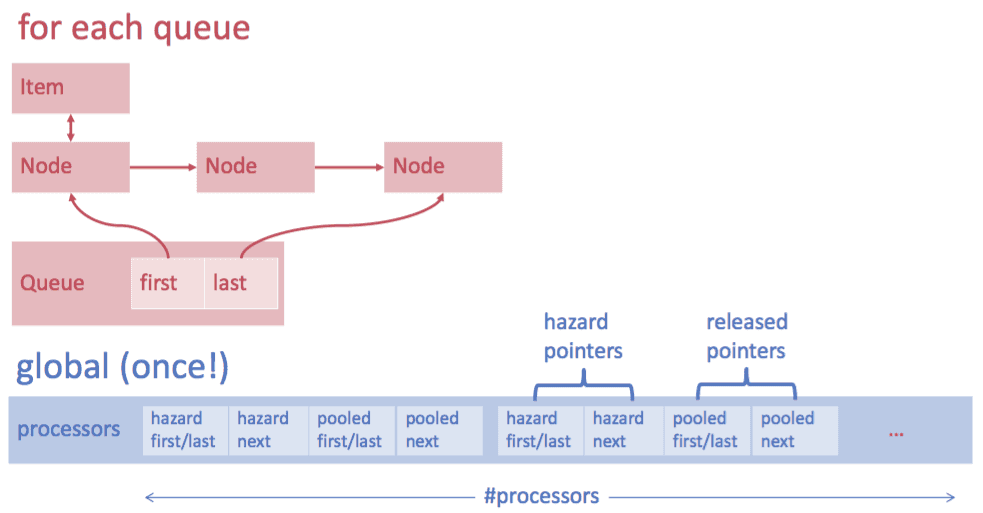
This image is taken from the lecture slides provided by Felix Friedrich
- Hazard Pointers: in use (writing)
- Pool: Reuse nodes that are not used anymore
- Lock-free but not wait-free (starvation possible)
- if not possible to en-/dequeue: help other threads (processors)
Scheduling (Activities)
TYPE Activity* = OBJECT {DISPOSABLE} (Queues.Item) (* Queues.Item accessed via activity register *)
VAR
    (* access to current processor *)
    (* stack management *)
    (* quantum and scheduling *)
    (* active object *)
END Activity;
Task Switch Finalizer
Finest granular protection makes races possible that did not occur previously:
Need to pass information to the new thread.
current := GetCurrentTask()
next := Dequeue(readyqueue)
Enqueue(current, readyqueue)
(* Here an other thread can dequeue and run (on the stack of)
   the currently executing thread! *)
SwitchTo(next)- When switching to new thread
- Enqueue runs on new thread
- Call finalizer of previous thread
Solution with finalizer:
SwitchTo (nextActivity, Enqueue,  (* Enqueue runs on new thread *)
          ADDRESS OF readyQueue[currentActivity.priority]);
FinalizeSwitch; (* Calls finalizer of previous thread *)
Stack Management
- Stacks organized as Heap Blocks
- Stack check instrumented at beginning of procedure
- Stack expansion is possible
- Possibilities to expand stack:
- Allocate more memory for stack, copy old stack to beginning of new (pointers to stack need to be updated
VARparameters) - Manage stack in a linked list, link to new portion of stack from the old one:
ReturnToStackSegmentfunction needed to go back to previous stack segment
- Allocate more memory for stack, copy old stack to beginning of new (pointers to stack need to be updated
Interrupts
- First Level IRQ by non-portable CPU module
- Second level IRQ handling with activities
Wait for interrupt:
Interrupts.Await(interrupt);First level IRQ code affecting scheduler queues runs on a virtual processor
PROCEDURE Handle (index: SIZE);
BEGIN {UNCOOPERATIVE, UNCHECKED}
    IF previousHandlers[index] # NIL THEN
        previousHandlers[index] (index)
    END;
    Activities.CallVirtual(NotifyNext,
                           ADDRESS OF awaitingQueues[index],
                           processors[index]);
END Handle;- Very powerful to write IRQ handlers in to levels
- Possible with cooperative multitasking
Lock-Free Memory Management
- Allocation/Deallocation by lock-free algorithms
- Buddy system: old approach but simple when returning blocks and merging them in free memory
- Mark-and-sweep
- Traverse heap and mark used blocks
- Remove all unmarked blocks
- Multiple garbage collectors can run in parallel
- Precise: doesn’t delete used blocks by accident (can happen in GC with heuristics)
- Optional
- Incremental: Possible to run on a subset all blocks (on different parts of heap)
- Concurrent: GC can run in concurrency of a mutating thread
- Parallel: Several instances of the GC can run at once
Data Structures:
| Global | Per Object | |
|---|---|---|
| Mark Bit | Cycle Count | Cycle Count |
| Marklist | Marked First | Next Marked |
| Watchlist | Watched First | Next Watched |
| Root Set | Global References | Local Refcount |
- Cycle Count: used to mark visited objects
- Mark List: all objects that were marked previously
- Watch List: all candidates that could be garbage collected
- Root Set: where to start to find all reachable object
Portability
- Lock-free A2 kernel written exclusively in a high-level language
- No timer interrupt required (cooperative multitasking): scheduler hardware independent
- No virtual memory
- no separate address spaces
- everything runs in user mode, all the time
- Hardware-dependent functions (CAS) are pushed into the language
- Almost completely portable:
- Some minimal stub written in assembly code to initialize memory mappings and initialize all processors
Oberon RISC (Case Study 3)
- RISC architecture
- Oberon OS
- Motivation: Build system from scratch
- Understanding a big amount of details
- Commercial systems are far from perfect
- Need good tools for programming
- Competence for building from Scratch: HW, application, how it really works
- ‘lean systems’ approach
- Build from scratch
- reduce complexity: no ‘baggage’
- choices of different implementation
- design based only on problem domain and experience
- less surprises!
- flexible solutions
- more than customer needs
- competitive advantages
- Why not build from scratch
- re-inventing the wheel
- fundamental knowledge required
- more actual work (the first time)
- restricted component choices
- not for short-term!
- team work: communication!
- Configurable Hardware
- PAL’s / GAL’s / CPLD’s
- LUT and interconnect
- Current: FPGA
- loadable configuration (not like ASIC/VLSI)
- Introduction to HDL:
- Simulation / Synthesis
- Verilog / VHDL
- Developed at ETH: Lola, ActiveCells
- Very different from Programming Languages
- Things happen in parallel (not serial)!
- Very difficult for high frequencies
- RISC architecture (overview)
- Documentation
- Developed by N. Wirth
- Used for book “Compiler Construction” by N. Wirth
- RISC vs. CISC
- Harward vs. Von Neumann
- Registers vs. Stack Machine
- FPU
- ALU
- Shifter (Barrel-Shifter)
- Implemented in Verilog
- 3 kinds of instructions - arithmetic/logic - load/store - floating-point
- RISC processor executes SW
- RISC0:
- Memory addressed as words
- RISC5:
- Memory can be addressed as bytes
- Adds external static RAM
- FPU
- SPI, PS/2, GPIO, RS-233, 1 ms timer
- Top of stack: -64
- Flags:
- Not equal
- Zero
- Carry/Borrow
- Overflow
- Co-design: OS/HW/Compiler
- Minimalistic
- Best practices from CS
- Architecture/Features
- Fast file system, module loader, garbage collector
- High-level, type-save language
- files
Module.Command[params]execution from any visual text- self hosted, small (~200kB)
- User Interface
- Mouse oriented, three buttons, “interclicking”
- Oberon Core System
- Inner/Outer core
- File system: FileDir, File
- Networking
- Outer core: input, viewers, fonts, text, …
- Compiler: recursive descent, single pass
- RS-232, SCC, Net
- no memory protection
- possible to draw over other windows
- no auto save
- Boot loader
- loads boot file (inner core) form SD-card (or serial port)
- Simple to build own tools build on Oberon System
- RISC emulator available
Active Cells (Case Study 4)
-
Custom design of Multi-Processor System
- Cores
- Caches
- Bus
- Memory
-
Each process owns it’s core
- Scheduling unnecessary
- Caches unnecessary
- some restrictions / some improvements
-
Tiny Register Machines (TRM)
- TRM interconnects
- SW/HW Co-design
- Active Cells Tool-chain
-
Multi-core Systems Challenges
- Cache coherence
- Shared memory communication bottleneck
- Thread synchronization overhead
- Difficult to predict behaviour and timing
- Hard to scale
- Partitioned Global Address Space
-
Operating System Challenges
- Processor Time Sharing
- Interrupts
- Context Switches
- Thread Synchronisation
- Memory Sharing
- Inter-process: Paging
- Intra-process, Inter-Thread: Monitors
- Processor Time Sharing
-
Project Supercomputer in the Pocket
- Focus: Streaming Applications (i.e ECG)
- Stream Parallelism (pipelining)
- Task parallelism / data parallelism
-
On-chip distributed system
- Replace shared memory by local memory
- Message passing for interaction between processes
- Separate processor for each process
- Very simple processors
- No scheduling, no interrupts
- Application-aware processors
- Minimal operating system
- Conceptually no memory bottleneck
- Higher reliability and predictability by design
- Replace shared memory by local memory
Tiny Register Machine (TRM)
- Extremely simple processor on FPGA
- Hardware architecture
- Two-stage pipeline
- Each TRM contains
- ALU and shifter
- 32-bit operands and results stored in a bank of 2 * 8 registers
- Local data memory: d * 512 words of 32 bits
- Local program memory: i * 1024 instructions with 32 bits
- 7 general purpose registers
- Register H for storing the high 32 bits of a product
- 4 conditional registers: C, N, V, Z
- no chaches
TRM Machine Language
- Machine language: binary representation of instructions
- 18-bit instructions
- Three instruction types:
- Type a: arithmetical and logical operations
- Type b: load and store instructions
- Type c: branch instructions (for jumping)
- Instruction Encoding: Offset and Immediate values have restricted width
- Long jumps constructed from chains
- Immediate store/load with shifts
- Variants of TRMs
- FTRM: includes FPU
- VTRM: includes vector processing unit
- 8 x 8-words registers
- available with/without FPU
- TRM with SW configurable instruction width
- First Experiment: TRM12
- Message passing architecture
- Bus based on chip interconnect
- Not scalable
- Second Experiment: Ring of 12 TRMs
- TRM ↔ Adapter ↔ Ring
- Not scalable
- Large delays
Active Cells
- Computing model, programming language
- Compiler, synthesizer, hardware library, simulator
- Programmable HW (FPGA)
- One tool-chain for SW and HW
- Consequences
- No global memory
- No processor sharing
- No peculiarities of specific processor
- No predefined topology (NoC)
- No interrupts
- No operation system
- Computation units: Cells
- Different parallelism levels:
- Communication Structure (Pipelining, Parallel Execution)
- Cell Capabilities (Vector Computing, Simultaneous Execution)
- Inspired by: Kahn Process Networks, Dataflow Programming, CSP
- Active Cell Component
- Active Cell
- Object with private state space
- Integrated control thread(s)
- Connected via channels
- Cell Net
- Network of communication cells
- Active Cell
- Active Cells
- Scope and environment for a running isolated process
- Cells do not share memory
- Defined as types with port parameters
Example:
TYPE
    Adder = cell (in1, in2: port in; result: port out); (* communication ports *)
    VAR summand1, summand2: integer;
    BEGIN
        in1 ? summand1; (* blocking receive *)
        in2 ? summand2;
        result ! summand1 + summand2; (* non-blocking send *)
    END Adder;
Cell Constructors to parameterize cells during allocation time:
TYPE
    Filter = cell (in: port in; result: port out);
    VAR ...; filterLength: integer;
    PROCEDURE & Init(filterLength: integer)  (* constructor *)
    BEGIN self.filterLength := filterLength
    END Init;
BEGIN
    (* ... filter action ... *)
END Filter;

VAR filter: Filter;
BEGIN
    .... new(filter, 32); (* initialization parameter filterlength = 32 *)
Cells can be parametrized with capabilities or non-default values:
TYPE
  (* Cell is a VectorTRM with 2k of Data Memory and has access to DDR2 memory *)
  Filter = cell {Vector, DataMemory(2048), DDR2} (in: port in (64); result: port out);
                                         (* in port is implemented with width of 64 bits *)
  VAR ...
  BEGIN
      (* ... filter action ... *)
END Filter;- Hierarchic Composition: Cell Nets
- Allocation of cells:
newstatement - Connection of cells:
connectstatement - Ports of cells can be delegated to the ports of the net:
delegatestatement - Terminal or closed Cellnets (i.e Cellnets without ports) can be deployed to hardware
- Allocation of cells:
Terminal Cellnet Example
cellnet Example;
import RS232;
TYPE
    UserInterface = cell {RS232}(out1, out2: port out; in: port in)
    (* ... *)
    END UserInterface;

    Adder = cell(in1, in2: port in; out: port out)
    (* ... *)
    END Adder;
    VAR interface: UserInterface; adder: Adder
    BEGIN
        new(interface);
        new(adder);
        connect(interface.out1, adder.in1);
        connect(interface.out2, adder.in2);
        connect(adder.result, interface.in);
END Example.- Communication between cells (CSP)
- Receiving is blocking (
?) - Sending is non-blocking (
!)
- Receiving is blocking (
- Engine Cell Made From Hardware (in HW library for FPGA)
-Hardware Library - Computation Components - General purpose minimal machine: TRM, FTRM - Vector machine: VTRM - MAC, Filters etc. - Communication Components (FIFOs) - 32 * 128 - 512 * 128 - 32, 64, 128, 1k * 32 - Storage Components - DDR2 controller - configurable DRAMs - CF controller - I/O Components - UART controller - LCD, LED controller - SPI, I2C controller - VGA, DVI controller
Programming Language vs. HDL
Programming Language
- Sequential execution
- No notion of time
Example:
VAR a,b,c: INTEGER;
a := 1;      (* unknown *)
b := 2;      (* mapping to *)
c := a + b;  (* machine cycles *)
Hardware Description Language
Continuous execution (combinational logic):
wire [31:0] a,b,c;
assign c=a+b; // no
assign a=1;   // memory
assign b=2;   // associated
Synchronous execution (register transfer):
reg [31:0] a,b,c;

always @ (posedge clk)
begin
    a <= 1;    // synchronous at
    b <= 2;    // rising edge
    c <= a+b;  // of the clock
end;
Single/Cycle Datapath (TRM)
Instruction Fetch
- Get value of PC
- Get data from instruction memory (36-bit)
- keep only upper or lower part (16-bit)
- depending on value of PC
- On clock
- if reset: PC := 0
- if stall: PC := PC
- else: PC := pcmux (set new PC)
Register Read
Read source operands from register file
wire [2:0] rd, rs;
wire regWr;
wire [31:0] rdOut, rsOut;
source register

// register file
// ...

assign irs = IR[2:0];      // source register
assign ird = IR[13:11];
assign dst = (BL)? 7: ird; // destination register- For
BLthe destination register is always the link register (7) - Otherwise the registers are read from the instuction register (IR)
ALU
Compute the result via ALU
wire [31:0] AA, A, B, imm;
wire [32:0] aluRes;

assign A = (IR[10])? AA: {22'b0, imm}; // bit 10: immediate or register

assign minusA = {1‘b0, ~A} + 33‘d1;
assign aluRes =
(MOV)? A:
(ADD)? {1‘b0, B} + {1‘b0, A} :
(SUB)? {1‘b0, B} + minusA :
(AND)? B & A :
(BIC)? B & ~A :
(OR)? B | A :
(XOR)? B ^ A :
~A;
Control Path
Control Path
assign vector = IR[10] & IR[9] & ~IR[8] & ~IR[7];
assign op = IR[17:14];

assign MOV = (op == 0);
assign NOT = (op == 1);
assign ADD = (op == 2);
assign SUB = (op == 3);
assign AND = (op == 4);
assign BIC = (op == 5);
assign OR = (op == 6);
assign XOR = (op == 7);
assign MUL = (op == 8) & (~IR[10] | ~IR[9]); assign ROR = (op == 10);
assign BR = (op == 11) & IR[10] & ~IR[9]; assign LDR = (op == 12);
assign ST = (op == 13);
assign Bc = (op == 14);
assign BL = (op == 15);
assign LDH = MOV & IR[10] & IR[3]; assign BLR = (op == 11) & IR[10] & IR[9];| IR[17:14] | Function |
|---|---|
| 0000 | B := A |
| 0001 | B := ~A |
| 0010 | B := B + A |
| 0011 | B := B – A |
| 0100 | B := B & A |
| 0101 | B := B & ~A |
| 0110 | B := B |
| 0111 | B := B ^ A |
Write Result Back to Rd
wire [31:0] regmux; wire regwr;

// ...

assign regwr = (BL | BLR | LDR & ~IR[10] |
    ~(IR[17] & IR[16]) & ~BR & ~vector)) & ~stall0;

assign regmux =
(BL | BLR) ? {{{32-PAW}{1'b0}}, nxpc}:
(LDR & ~IoenbReg) ? dmout:  // data memory out
(LDR & IoenbReg)? InbusReg: // from IO
(MUL) ? mulRes[31:0]:
(ROR) ? s3:
(LDH) ? H:
aluRes;
TRM Stalling
- Stop fetching next instruction, pcmux keeps the current value
- Disable register file write enable and memory write enable signals to avoid changing the state of the processor
- Only
LDandMULinstructions stall the processor - dmwe signal is not affected
- regwr signal is affected
Load (LD)
wire [31:0] dmout;
wire [DAW:0] dmadr;
wire [6:0] offset;
reg IoenbReg;

// register file
// ...
// src register = lr (7) ignored: harward architecture
Assign dmadr = (irs == 7) ? {{{DAW-6}{1'b0}}, offset} :
    (AA[DAW:0] + {{{DAW-6}{1'b0}}, offset});
assign ioenb = &(dmadr[DAW:6]); // I/O space: uppermost 2^6 bytes in data memory
assign rfWd = ...
    (LDR & ~IoenbReg)? dmout:
    (LDR & IoenbReg)? InbusReg: //from IO
    ...;

always @(posedge clk)
    IoenbReg <= ioenb;
Store (ST)
wire [31:0] dmin;
wire dmwr;
// register file
// ...

DM #(.BN(DMB)) dmx (.clk(clk),
    .wrDat(dmin),
    .wrAdr({{{31-DAW}{1'b0}},dmadr}),
    .rdAdr({{{31-DAW}{1'b0}},dmadr}),
    .wrEnb(dmwe),
    .rdDat(dmout));

assign dmwe = ST & ~IR[10] & ~ioenb;
assign dmin = B;
Set Flag Registers
always @ (posedge clk, negedge rst) begin // flags handling
if (~rst) begin N <= 0; Z <= 0; C <= 0; V <= 0; end
else begin
    if (regwr) begin
        N <= aluRes[31];
        Z <= (aluRes[31:0] == 0);
        C <= (ROR & s3[0]) | (~ROR & aluRes[32]);
        V <= ADD & ((~A[31] & ~B[31] & aluRes[31])
            | (A[31] & B[31] & ~aluRes[31]))
            | SUB & ((~B[31] & A[31] & aluRes[31])
            | (B[31] & ~A[31] & ~aluRes[31]));
    end
end
end
Branch instructions
- PC <= PC + 1 + off
- PC <= Rs
- PC <= PC + 1 (by default)
- PC <= PC (if stall)
- PC <= 0 (reset)
Code:
// pcmux logic
assign pcmux =
    (~rst) ? 0 :
    (stall0) ? PC:
    (BL)? {{10{IR[BLS-1]}},IR[BLS-1: 0]}+ nxpc :
    (Bc & cond) ? {{{PAW-10}{IR[9]}}, IR[9:0]} + nxpc : (BLR | BR ) ? A[PAW-1:0] :
    nxpc;
Separate Compilation (TRM)
- Development environment with separate compilation
- important for commercial products
- state of the art
- Very limited architecture
- 18-bit instructions
- 10-bit immediates
- 7-bit memory offset
- 10bit (signed) conditional branch offset
- 14-bit (+/- 8k) Branch&Link
- long jumps (chained)
- immediates -> expressed by several instructions or put to memory (fixups)
- fixups, problematic if large global variables are allocated
- Solution: Compilation to Intermediate Code, back-end application at link time
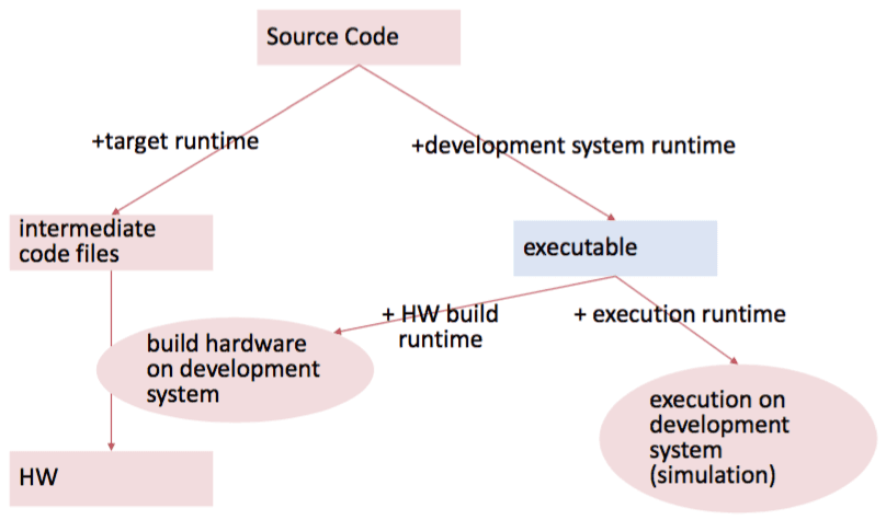
Compilation Steps
- Scanner & Parser
- Checker
- Intermediate Back-end
- Intermediate Object File
- Active Cells Back-end
- Active Cells Specification, Intermediate Assembler
- Target Back-end
- Generic Object File Linker
Problems with Active Cells 1
- What if several same HW components available?
- How to extend HW without rewriting compiler each time?
Generic Communication Interface
- Peer-to-Peer
- Use of AXI4 Stream interconnect standard from ARM
- Generic, flexible
- Non-redundant
Active Cells 2
- Flexible parameterization of the components using interpreted code in the component specification
- XML-based specification (object persistency)
Active Cells 3
- Parameterization and Description of Hardware completely in one programming language
- Platform specific settings clock sources, pin locations etc
- Component specific settings:
- dependencies (Verilog-Files) parameters
- port names
- Can be made very generic with plugins
This image is taken from the lecture slides provided by Felix Friedrich